A Real Engineering Case Study on Core Pull Force, Plastic Adhesion and Hydraulic Cylinder Selection
Introduction
Selecting the correct hydraulic cylinder for an injection mold is far more complex than simply choosing a bore diameter capable of generating sufficient force. Every year, mold manufacturers experience failures caused by undersized cylinders, excessive hydraulic pressure, poor slide synchronization, premature wear or incomplete core movement. In most situations, these problems are not related to the hydraulic cylinder itself but to an incorrect engineering calculation performed during the design stage.
The movement of side cores and slides is one of the most critical operations inside an injection mold. During mold opening and closing, hydraulic cylinders must overcome not only the injection pressure acting on the plastic component but also the adhesion forces generated between the polymer and the steel surfaces. These forces vary significantly depending on the molded material, the geometry of the core, the draft angle, the cooling conditions and the timing of the extraction sequence.
A common mistake is to calculate only the pushing force required to resist cavity pressure while completely ignoring the extraction force required to pull the core out of the molded part. In many engineering applications, the extraction force is actually greater than the pushing force. Ignoring this phenomenon often results in selecting a hydraulic cylinder capable of moving the slide during mold closing but unable to extract it reliably after molding.
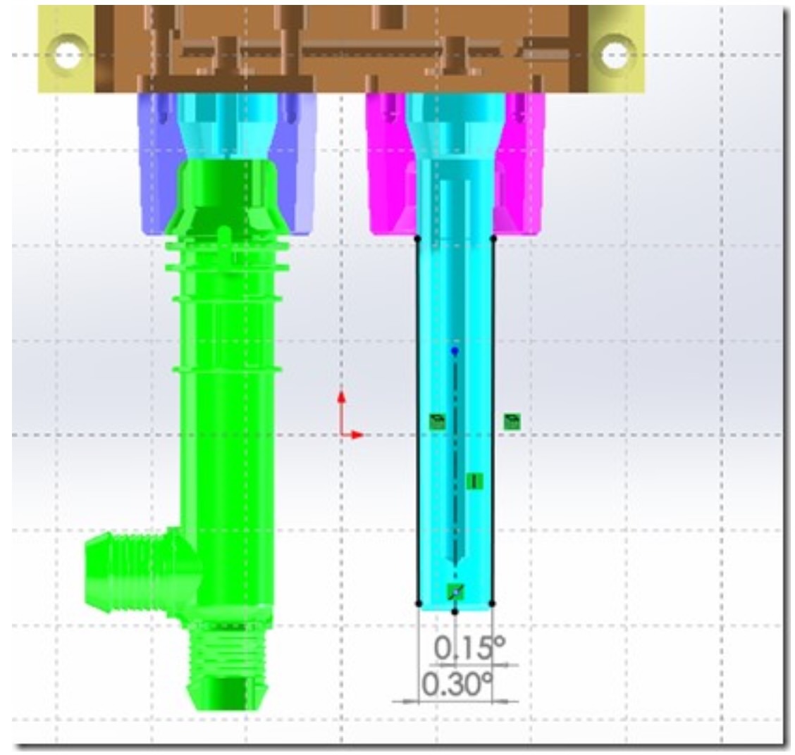
The real engineering case presented in this article perfectly illustrates this situation. A mold manufacturer requested assistance in selecting the correct hydraulic cylinder for an injection mold processing PP reinforced with 30% glass fiber (PP+GF30). The initial calculations underestimated the required force because they considered only one moving core, while the mold actually contained two identical cores driven simultaneously by a single hydraulic cylinder. After reviewing the three-dimensional model, the Vega engineering department recalculated both thrust and extraction forces and recommended a different cylinder configuration based on the available hydraulic pressure.
This case demonstrates why hydraulic cylinder sizing should always be treated as a complete engineering calculation rather than a simple force estimate.
Understanding the Forces Acting on a Core Slide
A hydraulic cylinder driving a core slide performs two completely different mechanical tasks.
During mold closing and injection, it must keep the slide firmly positioned against the enormous forces generated by the molten polymer.
During mold opening, however, the cylinder must overcome the adhesion between the molded part and the steel core before the slide can retract.
Although these two movements occur within the same molding cycle, the forces involved are generated by completely different physical phenomena.
The thrust force depends mainly on cavity pressure acting over the projected frontal area of the core.
The extraction force depends on friction, shrinkage and polymer adhesion acting over the entire lateral contact surface.
Because these mechanisms are different, they must always be calculated separately.
Calculating the Thrust Force
The thrust force is generated by the pressure of the molten polymer acting against the frontal surface of the core.
The classical engineering equation is:
F = P × A
Where:
F = thrust force
P = cavity pressure
A = projected frontal area
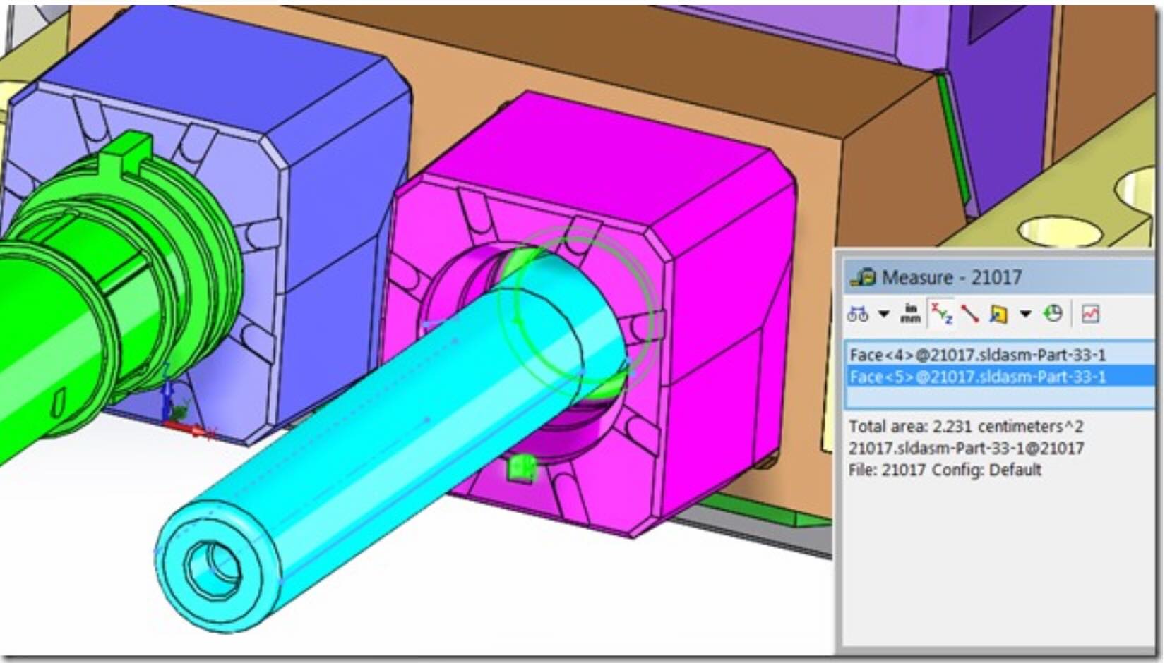
In the analyzed case, the frontal area of each core was approximately 2.23 cm².
The molding pressure was estimated at 500 bar.
However, the initial calculation considered only one core.
After reviewing the 3D model, Vega engineers observed that a single hydraulic cylinder moved two identical cores, doubling the projected area and therefore doubling the required thrust force.
The corrected nominal thrust force became approximately 2230 kgf instead of the previously calculated 1115 kgf.
This correction completely changed the hydraulic cylinder selection.
Why the Number of Moving Cores Matters
This case highlights one of the most common design mistakes encountered in hydraulic cylinder sizing.
Designers often calculate the force required for a single moving component without considering that one cylinder may simultaneously move several mechanical elements linked together.
Whenever two slides, two cores or multiple mechanical actions are connected to the same actuator, every resisting force must be summed.
Ignoring this principle immediately produces an undersized cylinder.
The hydraulic system may initially appear to function correctly during mold trials, but once production conditions stabilize, pressure peaks, temperature changes and plastic shrinkage expose the insufficient safety margin.
This is exactly why every moving element connected to a hydraulic cylinder must be included in the engineering calculation.
Calculating the Extraction Force
If thrust force calculations are relatively straightforward, extraction force calculations are considerably more complex.
When the molded component cools inside the cavity, the polymer shrinks around the steel core.
At the same time, microscopic adhesion develops between the polymer surface and the polished steel.
The hydraulic cylinder must overcome both phenomena before extraction can begin.
The resisting force depends primarily on:
- lateral contact area;
- plastic adhesion coefficient;
- polymer shrinkage;
- draft angle;
- surface finish;
- extraction temperature.
Unlike cavity pressure, which disappears after injection, adhesion remains until the part separates from the steel.
The Importance of the Contact Surface
One of the most important concepts in core pull calculations is the distinction between projected area and contact area.
The projected frontal area determines the pushing force.
The lateral surface determines the extraction force.
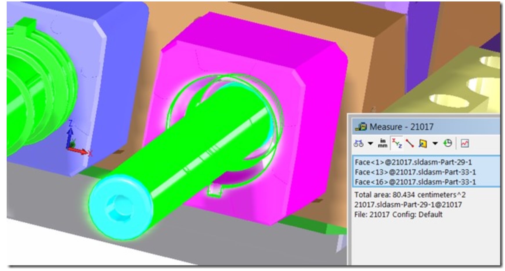
In the engineering case, each core presented approximately 80.43 cm² of lateral contact surface.
Again, because two identical cores were moved simultaneously, the total effective contact area doubled.
Using an adhesion coefficient of 20 kg/cm², Vega engineers calculated a nominal extraction force of approximately 3217 kgf, almost 45% higher than the pushing force.
This result surprises many designers.
Why Extraction Force Is Usually Higher
Many engineers expect the injection pressure to represent the worst loading condition.
In reality, extraction frequently requires more force.
Several physical mechanisms contribute simultaneously:
The polymer shrinks during cooling.
Glass fibers increase stiffness.
The material grips the steel core.
Microscopic surface roughness increases friction.
Vacuum effects may develop inside deep cavities.
These phenomena combine to produce extraction loads that often exceed cavity pressure loads.
Consequently, hydraulic cylinders should always be selected according to the highest expected operating force rather than the injection force alone.
The Effect of Draft Angle
Draft angle has an enormous influence on extraction force.
A perfectly cylindrical core without draft generates the highest friction because the contact pressure remains constant along the entire length.
Even a small draft angle significantly reduces the normal force acting between plastic and steel.
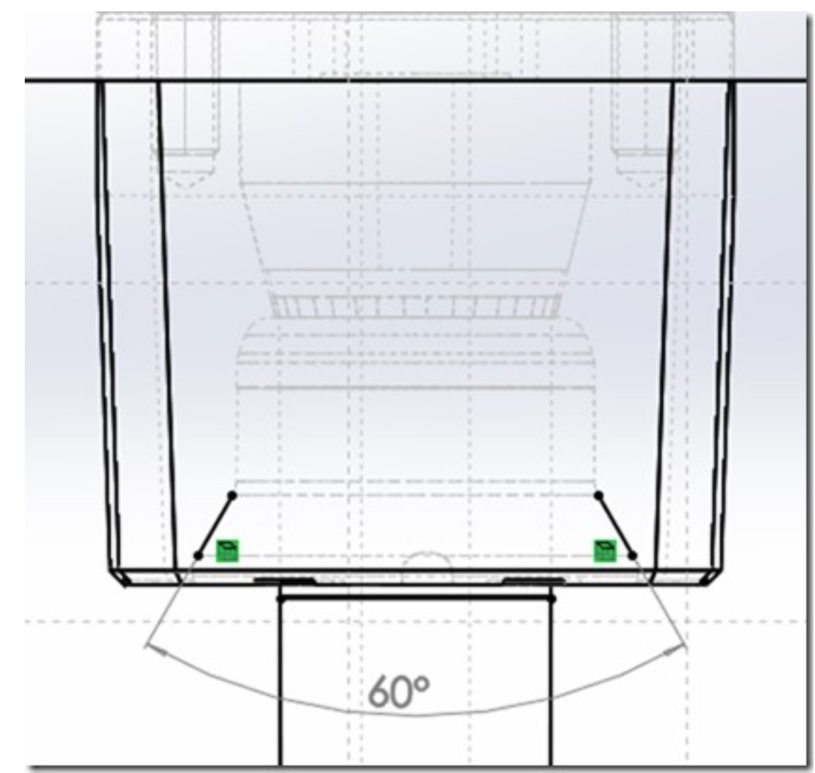
In the analyzed mold, the draft angle was approximately 0.3°, a relatively small value.
Because of this limited draft, Vega engineers adopted an adhesion coefficient of 20 kg/cm², providing an adequate engineering safety margin for PP reinforced with glass fiber.
For materials with higher shrinkage or rougher surfaces, different coefficients may be required.
Temperature Changes Everything
Extraction force is not constant throughout the molding cycle.
Immediately after injection, the polymer is soft and adhesion is relatively low.
As cooling progresses, shrinkage increases the radial pressure acting on the core.
Eventually the adhesion reaches its maximum.
Later, when the molded part continues cooling after mold opening, thermal contraction decreases and extraction becomes easier.
For this reason extraction timing has a direct influence on hydraulic cylinder sizing.
The Vega engineering report specifically notes that the actual extraction force decreases according to the temperature of the molded component during the pulling phase, while the calculated nominal value intentionally provides a conservative safety margin.
This conservative approach is standard engineering practice.
Choosing the Hydraulic Cylinder
Once thrust and extraction forces have been determined, the designer can select the hydraulic cylinder.
The required piston force depends on:
- available hydraulic pressure;
- piston area;
- safety factor;
- mechanical efficiency.
Because hydraulic force is proportional to piston area, increasing cylinder diameter allows lower operating pressure.
In the analyzed project, Vega engineers proposed two alternative solutions.
A CR063028 cylinder could operate at approximately 130 bar.
Alternatively, a larger CR080036 cylinder could produce the same mechanical output using only 90 bar hydraulic pressure.
Both solutions satisfy the force requirement but offer different compromises between size, available pressure and hydraulic system design.
Safety Factors
Engineering calculations should never be based solely on theoretical forces.
Real production conditions introduce unavoidable uncertainties.
Material batches vary.
Surface finishes change.
Lubrication differs.
Cooling conditions fluctuate.
Hydraulic pressure oscillates.
For these reasons hydraulic cylinders should always include an adequate safety factor.
Excessive safety factors unnecessarily increase cylinder size, cost and cycle time.
Insufficient safety factors dramatically increase the probability of production failures.
Selecting the correct margin is therefore an engineering optimization problem rather than a simple mathematical calculation.
Common Design Mistakes
Technical support departments repeatedly encounter the same errors during hydraulic cylinder selection.
Among the most frequent are:
- calculating only one moving slide instead of the complete mechanical system;
- ignoring extraction force;
- using unrealistic cavity pressure values;
- neglecting plastic adhesion;
- forgetting the influence of draft angle;
- selecting cylinders without considering available hydraulic pressure;
- applying inadequate safety factors.
Most hydraulic cylinder problems originate from these engineering mistakes rather than from manufacturing defects.
Engineering Lessons Learned
This engineering case clearly demonstrates that selecting a hydraulic cylinder cannot be reduced to reading a catalog.
A proper design requires understanding the interaction between polymer behavior, mold geometry, hydraulic pressure and mechanical transmission.
The most important lesson from this project was not the final cylinder selected.
It was the discovery that two cores, rather than one, were driven simultaneously by the same hydraulic actuator.
That single observation doubled the required thrust force, doubled the extraction force calculation and completely changed the recommended hydraulic cylinder.
Without reviewing the complete three-dimensional assembly, this critical detail would likely have remained unnoticed.
Conclusions
Hydraulic cylinder sizing for injection molds is a multidisciplinary engineering activity involving polymer processing, mechanical engineering and hydraulic system design.
Although force calculations appear simple, reliable cylinder selection requires careful evaluation of cavity pressure, projected area, adhesion forces, draft angle, extraction timing, available hydraulic pressure and safety margins.
The real engineering case presented in this article illustrates how a seemingly minor assumption—considering one moving core instead of two—can completely alter the final design.
By systematically calculating both thrust and extraction forces and validating every assumption against the actual mold geometry, engineers can select hydraulic cylinders that operate reliably throughout millions of molding cycles.
Accurate engineering calculations performed during the design phase remain the most effective method for preventing costly production problems, reducing maintenance and ensuring long-term mold reliability.