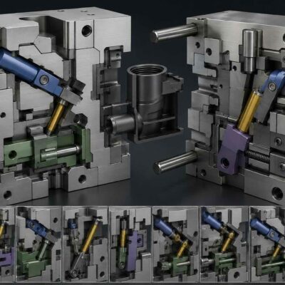
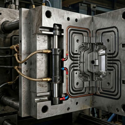
Calculating the Real Forces Acting on Mold Slides
Selecting a locking cylinder for an injection mold is often considered a straightforward task. Many designers simply choose a cylinder based on the available installation space or by comparing it with solutions used in previous projects.
In reality, selecting the correct locking cylinder is a structural engineering problem that requires understanding how molten plastic generates forces inside the mold.
A cylinder that is too small may allow the slide to move during injection, causing flash, dimensional inaccuracies or even severe damage to the mold.
Conversely, an oversized cylinder increases costs, occupies unnecessary space and may generate excessive mechanical loads throughout the slide mechanism.
The correct solution begins with engineering calculations rather than intuition.
A real engineering case handled by the Vega Engineering Team perfectly illustrates this approach.
A Practical Engineering Case
A customer requested assistance in selecting the appropriate locking cylinders for an injection mold.
Rather than immediately recommending a cylinder, the Vega Engineering Team first analysed the mold drawings.
During this review, the engineers identified an important design consideration.
The connection between the hydraulic cylinder and the slide was relatively long.
Because every mechanical connection behaves elastically under load, the team recommended increasing the preload according to the maximum expected compression of the connection system before proceeding with the cylinder selection.
This observation may appear secondary.
In reality, it demonstrates an important engineering principle:
The hydraulic cylinder is only one element of the mechanical system. The stiffness of the entire load path determines the reliability of the locking system.
Only after analysing the complete mechanical arrangement did the engineers calculate the forces acting on each core.
Why Force Calculations Are Essential
During injection molding, molten plastic behaves like a pressurised fluid.
As cavity pressure increases, the polymer pushes against every exposed surface inside the mold.
Some surfaces generate opening forces.
Others generate closing forces.
Slides, lifters and locking cylinders must resist these forces without moving.
If the resisting force produced by the hydraulic cylinder is lower than the force generated by the plastic, the slide may move even a fraction of a millimetre.
That tiny movement is often sufficient to produce:
- flash on the molded part;
- dimensional defects;
- premature wear of shut-off surfaces;
- deformation of slide components;
- catastrophic damage in severe cases.
For this reason, professional mold designers never choose a locking cylinder by cylinder size alone.
They calculate the expected forces first.
Understanding the Origin of Injection Forces
The pressure inside the cavity acts perpendicular to every surface it contacts.
The force generated depends on only two parameters:
- cavity pressure;
- projected area exposed to the pressure.
The basic relationship is:
Word Equation Format
F=P×Awhere:
- F = force
- P = plastic pressure
- A = projected area
Although this equation is extremely simple, it forms the basis of virtually every locking cylinder calculation.
The challenge is not the equation itself.
The challenge is correctly identifying the surface that is actually subjected to injection pressure.
Core 1 – Calculating the Thrust Force
For the first core, the Vega Engineering Team determined that the projected frontal area exposed to cavity pressure was:
40.12 cm²
The estimated cavity pressure was:
500 bar
Using these values, the resulting thrust force was approximately:
20,000 kgf
Based on this calculation, the recommended solution was:
- CF056 locking cylinder with a maximum preload of 0.05 mm
- Alternative solution: CF071
Notice that the cylinder was not selected because it “looked appropriate.”
It was selected because its locking capacity exceeded the calculated mechanical load while also considering preload and the stiffness of the connection.
Why Preload Matters
One of the most interesting aspects of this engineering case is the recommendation to introduce preload.
Many engineers think of preload simply as eliminating mechanical clearance.
Its function is actually much more important.
Every mechanical connection behaves like a spring.
When an external force is applied, the connection compresses slightly.
If clearance exists before loading begins, the slide must first move until the clearance disappears.
Only afterwards can the cylinder begin resisting the injection force.
Preload eliminates this unwanted initial movement.
The result is:
- higher positioning accuracy;
- reduced impact loading;
- improved dimensional repeatability;
- lower fatigue stresses;
- longer service life of the locking system.
In this case, because the connection between the slide and the cylinder was relatively long, its elastic deformation would also be greater.
Increasing preload therefore compensated for this additional compliance.
Mechanical Compliance of the Load Path
The hydraulic cylinder itself is rarely the weakest component of the system.
The complete load path includes:
- cylinder body;
- piston rod;
- rod end;
- connecting screws;
- intermediate spacers;
- slide body;
- guide elements.
Each component undergoes a small elastic deformation under load.
Although each deformation is microscopic, the total deformation may become significant.
This phenomenon is known as system compliance.
Longer mechanical connections generally have lower stiffness.
Lower stiffness results in greater elastic displacement.
Consequently, the preload required to maintain a rigid locking system also increases.
This explains why experienced engineers evaluate the entire assembly rather than considering the hydraulic cylinder in isolation.
Core 2 – A Completely Different Force
The second slide produced a very different loading condition.
Its projected frontal area measured only:
7.35 cm²
With the same estimated cavity pressure of 500 bar, the calculated thrust force became approximately:
3,675 kgf, almost six times lower than Core 1.
At first glance, one might conclude that the design problem is solved.
However, another force also had to be considered.
The extraction force.
Why Slides Experience Extraction Forces
When the molded part begins to shrink during cooling, it grips the core surfaces.
This adhesion generates friction between the plastic and the steel.
As the slide retracts, the hydraulic cylinder must overcome not only its own mechanical resistance but also the adhesion of the molded material.
Unlike thrust force, which depends mainly on cavity pressure, extraction force depends on:
- contact surface;
- plastic material;
- shrinkage;
- surface finish;
- coefficient of adhesion.
For this application, the Vega Engineering Team calculated:
- lateral contact surface: 9.14 cm²
- adhesion coefficient: 20 kg/cm²
- resulting extraction force: approximately 183 kgf
This force is dramatically smaller than the injection thrust.
Nevertheless, it remains essential for selecting the correct cylinder because the cylinder must perform reliably in both directions.
Why Injection Pressure Is Only Part of the Story
Many engineers assume that the maximum injection pressure alone determines cylinder size.
In reality, cavity pressure is only one component of the loading condition.
A complete engineering analysis also considers:
- projected frontal area;
- lateral contact area;
- plastic adhesion;
- slide geometry;
- preload;
- elastic deformation of the mechanical connection;
- safety factors;
- dynamic loads generated during machine operation.
Ignoring any of these parameters can result in an undersized or oversized locking cylinder.
This explains why experienced engineering departments begin with force calculations before recommending any specific cylinder series.
Safety Factors, Mechanical Stiffness and Selecting the Right Locking Cylinder
In Part 1, we analysed how the Vega Engineering Team calculated the thrust and extraction forces acting on two mold cores before selecting the appropriate locking cylinders.
The calculations showed that Core 1 generated an injection force of approximately 20,000 kgf, while Core 2 required only about 3,675 kgf. The extraction force for Core 2, caused by plastic adhesion, was approximately 183 kgf.
Although these calculations identify the minimum forces acting on the slides, they do not automatically determine which hydraulic cylinder should be installed.
A professional design must still answer several important engineering questions.
- Is the calculated force sufficient?
- Should a safety factor be applied?
- How much preload is required?
- Will the mechanical connection deform under load?
- Will the cylinder continue to lock the slide after millions of production cycles?
These questions distinguish engineering from simple component selection.
The Difference Between Calculated Force and Required Cylinder Force
One of the most common mistakes in mold design is selecting a cylinder whose nominal force is equal to the calculated injection force.
This leaves virtually no engineering margin.
In reality, the cylinder must compensate not only for the theoretical load but also for numerous uncertainties that occur during production.
These include:
- fluctuations in cavity pressure;
- variations in material viscosity;
- pressure spikes during filling;
- wear of the slide guides;
- manufacturing tolerances;
- elastic deformation of the complete locking system.
For this reason, engineers normally apply a safety factor.
The required cylinder force can be estimated as:
Word Equation Format
F_required=F_calculated×SFwhere:
- F_required = minimum cylinder capacity
- F_calculated = calculated mechanical load
- SF = safety factor
Depending on the application, safety factors between 1.2 and 2.0 are commonly used.
Critical applications with severe dynamic loading may require even larger margins.
The objective is not to oversize the cylinder unnecessarily.
The objective is to ensure reliable operation throughout the entire service life of the mold.
Why Injection Pressure Is Never Constant
Many engineering calculations assume a constant cavity pressure.
Actual molding conditions are considerably more complex.
During every molding cycle, cavity pressure changes continuously.
The pressure increases rapidly during filling.
It reaches a peak during packing.
It gradually decreases while the polymer cools.
The hydraulic cylinder therefore experiences a continuously changing load rather than a single constant force.
Furthermore, the machine itself may generate transient pressure peaks that exceed the nominal processing conditions.
For this reason, experienced engineers design for the maximum expected operating condition, not for the average cycle.
The Importance of Dynamic Loads
Static calculations provide only part of the answer.
Industrial machinery is dynamic.
Slides accelerate and decelerate.
Hydraulic valves open and close rapidly.
Mechanical clearances are repeatedly loaded and unloaded.
Every acceleration produces inertia forces.
These dynamic forces are added to the hydraulic forces already acting on the locking system.
Consequently, the cylinder may experience loads significantly higher than those predicted by static calculations alone.
Ignoring these dynamic effects often leads to premature wear, vibration and reduced fatigue life.
Why Stiffness Is Just as Important as Force
Many designers concentrate exclusively on cylinder force.
However, stiffness is equally important.
Imagine two cylinders capable of producing exactly the same locking force.
One is installed through a short, rigid connection.
The other operates through a long mechanical linkage.
Although the hydraulic force is identical, the second system will deform much more under load.
This additional deformation may allow microscopic movement of the slide.
Even movements of only a few hundredths of a millimetre can produce:
- flash;
- accelerated wear;
- reduced dimensional accuracy;
- damage to shut-off surfaces.
This explains why the Vega Engineering Team immediately noticed that the connection between the cylinder and the slide was too long and recommended increasing the preload.
The recommendation addressed the stiffness of the entire mechanical system, not simply the hydraulic cylinder.
The Role of Mechanical Deflection
Every mechanical component deforms elastically when subjected to force.
This deformation follows Hooke’s Law.
Word Equation Format
δ=(F×L)/(A×E)where:
- δ = elastic deflection
- F = applied force
- L = component length
- A = cross-sectional area
- E = Young’s Modulus
This equation clearly illustrates why long mechanical connections are less rigid.
As the length L increases, the elastic deflection increases proportionally.
Similarly, increasing the cross-sectional area or selecting materials with a higher Young’s Modulus reduces deformation.
Although actual slide mechanisms are more complex than a simple bar in tension, this equation helps explain the engineering principle.
Reducing mechanical compliance improves positioning accuracy and locking reliability.
Why Plastic Adhesion Cannot Be Ignored
Injection pressure is responsible for the largest loading during filling.
However, extraction loads dominate during mold opening.
As the polymer cools, it shrinks around the core surfaces.
The resulting adhesion creates friction between the molded part and the steel.
The hydraulic cylinder must overcome this resistance every cycle.
The magnitude of the extraction force depends on:
- plastic material;
- shrinkage;
- surface finish;
- draft angle;
- lubrication conditions;
- contact area.
Highly filled engineering plastics often produce greater adhesion than commodity polymers.
For this reason, engineers frequently consider worst-case material behaviour when sizing locking cylinders.
Why the Entire Mold Must Be Analysed
The hydraulic cylinder is only one component within a much larger mechanical system.
A proper engineering evaluation includes:
- cavity pressure;
- projected area;
- extraction force;
- preload;
- guide wear;
- support rigidity;
- slide alignment;
- mechanical tolerances;
- hydraulic pressure losses.
A perfectly sized cylinder cannot compensate for poor mechanical design elsewhere in the mold.
Likewise, increasing cylinder size rarely solves problems caused by insufficient structural stiffness.
The entire load path must be analysed as one integrated mechanical system.
Engineering Decisions Are Based on Calculations, Not Assumptions
One particularly valuable aspect of this engineering case is the systematic approach followed by the Vega Engineering Team.
Rather than recommending a cylinder based on experience alone, the engineers:
- examined the mold design;
- evaluated the mechanical connection;
- identified the need for additional preload;
- calculated the projected areas;
- estimated cavity pressure;
- calculated thrust forces;
- calculated extraction forces;
- recommended the most suitable cylinder for each core.
This engineering workflow dramatically reduces the probability of costly design errors.
Why Correct Cylinder Selection Reduces Total Production Costs
At first glance, performing detailed engineering calculations may appear time-consuming.
In reality, the opposite is true.
A correctly sized locking cylinder helps to prevent:
- mold repairs;
- production downtime;
- dimensional defects;
- flash;
- premature component replacement;
- warranty claims;
- repeated design modifications.
The cost of engineering analysis is almost always insignificant compared with the cost of correcting a mold after production has started.
This is one of the reasons why experienced mold manufacturers invest considerable time in force calculations during the design phase.
Conclusion
This engineering case demonstrates that selecting a locking cylinder is far more than choosing a component from a catalogue.
The correct selection begins with understanding how molten plastic generates forces inside the mold.
By calculating the projected areas, estimating cavity pressure, evaluating extraction forces and analysing the stiffness of the complete mechanical system, the Vega Engineering Team selected cylinders based on engineering evidence rather than assumptions.
Equally important, the engineers recognised that the relatively long connection between the cylinder and the slide required additional preload to compensate for elastic deformation. This recommendation illustrates an often-overlooked principle of mold design:
The reliability of a locking system depends not only on hydraulic force, but on the stiffness and behaviour of the entire mechanical load path.
Proper cylinder selection therefore combines mechanical engineering, material behaviour, hydraulic design and practical experience.
When these disciplines are integrated, the result is a mold capable of producing accurate parts consistently over millions of production cycles.
Related Articles
- https://www.icvega.com/promoting/hydraulic-core-pulling-guide
- https://www.icvega.com/choosing/choosing-the-right-cylinder-for-mold-core-pushing-force
- https://www.icvega.com/choosing/choosing-the-right-cylinder-for-mold-core-pulling-stroke
- https://www.icvega.com/support/the-2-millimeters-that-could-have-stopped-an-entire-mold
- https://www.icvega.com/support/a-safer-approach-to-oil-pressure-in-compact-hydraulic-cylinders