Why Hydraulic Cylinder Tubes Deform: Engineering Failure Analysis of a Real Injection Mold Case
Introduction
Hydraulic cylinders are among the most reliable components used in injection molds. Designed to operate under high pressure and withstand millions of operating cycles, they are generally considered maintenance-free when correctly selected and installed. Nevertheless, cylinder failures still occur, and one of the least understood is the permanent deformation of the cylinder tube.
When engineers discover a deformed cylinder, the first reaction is often to suspect a manufacturing defect or poor material quality. In reality, this is rarely the true cause. Experience from thousands of industrial applications shows that most cylinder failures originate from incorrect application rather than defective manufacturing.
A hydraulic cylinder never works alone. It is part of a complete mechanical system consisting of hydraulic valves, hoses, mold plates, guide elements, moving masses and the machine control sequence. Any design error affecting one of these elements can dramatically increase the stresses acting on the cylinder.
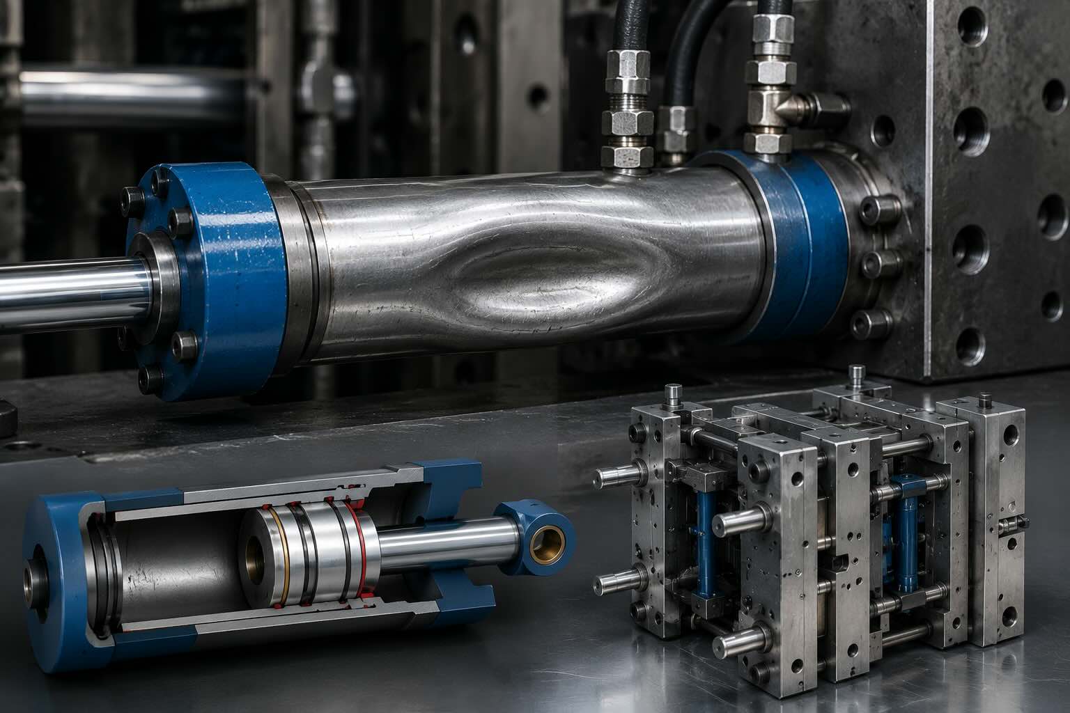
The engineering support case presented in this article demonstrates this principle. During production, a hydraulic cylinder installed inside an injection mold experienced permanent tube deformation. Instead of immediately replacing the cylinder, the engineering investigation focused on understanding the actual forces acting on the component and reconstructing the complete operating conditions.
This article expands that real support case into a complete engineering guide. Using hydraulic theory, mechanical calculations and practical mold design considerations, it explains why hydraulic cylinders deform, how these failures develop and how they can be prevented during the design stage.
Hydraulic Cylinders Are Rarely the Root Cause
Modern hydraulic cylinders are manufactured from high-strength alloy steels using precision machining processes. Cylinder tubes are honed to extremely tight tolerances, pistons are accurately fitted, rods are induction hardened and chrome plated, while sealing systems are designed to withstand millions of operating cycles.
Because of this robust construction, catastrophic failures are uncommon when cylinders operate within their design limits.
When permanent deformation occurs, engineers should avoid asking:
“Why did the cylinder fail?”
Instead, the correct engineering question is:
“Why was the cylinder subjected to loads exceeding its design limits?”
Most failures are caused by one or more of the following conditions:
- Incorrect cylinder sizing
- Underestimated moving mass
- High acceleration and deceleration
- Pressure intensification
- Trapped hydraulic oil
- Incorrect mold sequencing
- Side loading on the piston rod
- Mechanical misalignment
- Impact at the end of stroke
- Excessive hydraulic pressure peaks
Only after excluding these possibilities should the cylinder itself become the primary suspect.
The Real Engineering Case
The support case analyzed in this article involved a hydraulic cylinder responsible for moving one of the mold elements during the production cycle.
After an extended period of operation, one cylinder exhibited permanent deformation of the outer tube.
At first inspection, the damage appeared to indicate insufficient mechanical strength.
However, the engineering department followed a structured failure analysis procedure instead of simply replacing the component.
The investigation included:
- Verification of cylinder dimensions
- Evaluation of working pressure
- Calculation of theoretical hydraulic force
- Analysis of the moving plate mass
- Reconstruction of the mold operating sequence
- Verification of assembly conditions
- Evaluation of external mechanical loads
Only after understanding the complete mechanical system could the actual cause of the failure be identified.
This methodology represents one of the most important lessons for mold designers:
A hydraulic cylinder must always be analyzed as part of the complete mechanical system rather than as an isolated component.
Understanding Hydraulic Force
Every hydraulic cylinder converts hydraulic pressure into linear mechanical force.
The fundamental hydraulic equation is:
Equation 1 – Hydraulic Force
F = P × A
Where:
- F = Hydraulic force (N)
- P = Hydraulic pressure (Pa)
- A = Effective piston area (m²)
Although simple, this equation is frequently misused because many designers do not distinguish between extension force and retraction force.
Effective Piston Area
During extension, the complete piston surface is pressurized.
Equation 2 – Piston Area
Ap = (π × D²) / 4
Where:
- Ap = Piston area
- D = Piston diameter
During retraction, the piston rod occupies part of the piston area.
The effective hydraulic area therefore becomes:
Equation 3 – Annular Area
Ar = π × (D² − d²) / 4
Where:
- Ar = Annular area
- D = Piston diameter
- d = Rod diameter
Because the available area is smaller, the retraction force is always lower than the extension force.
Ignoring this difference is a common design mistake that often leads to undersized hydraulic systems.
Practical Engineering Example
Consider a hydraulic cylinder with the following specifications:
| Parameter | Value |
|---|---|
| Piston diameter | 32 mm |
| Rod diameter | 20 mm |
| Working pressure | 140 bar |
Step 1 – Calculate the piston area
Using Equation 2:
Ap = (π × D²) / 4
Substituting D = 32 mm:
Ap = (3.1416 × 32²) / 4
Result:
Ap = 804 mm²
Converting to SI units:
Ap = 0.000804 m²
Step 2 – Convert pressure
Working pressure:
140 bar
Since:
1 bar = 100,000 Pa
The hydraulic pressure becomes:
P = 14,000,000 Pa
Step 3 – Calculate hydraulic force
Using Equation 1:
F = P × A
Substituting the calculated values:
F = 14,000,000 × 0.000804
Result:
F = 11,256 N
or approximately:
F = 11.3 kN
At first glance, this force appears more than sufficient for many injection mold applications.
Unfortunately, this calculation considers only static loading.
Real injection molds almost never operate under purely static conditions.
Static Loads Represent Only Part of the Problem
Many engineers calculate the required hydraulic force by considering only the weight of the moving component.
This approach is incomplete.
Hydraulic cylinders do not simply support a static mass; they must accelerate, decelerate and stop moving mechanical components thousands of times every day.
According to Newton’s Second Law:
Equation 4 – Newton’s Second Law
F = m × a
Where:
- m = Moving mass (kg)
- a = Acceleration (m/s²)
Suppose the moving plate has a mass of 150 kg.
If it reaches a velocity of 0.40 m/s in 0.05 s, the acceleration is:
Equation 5 – Acceleration
a = Δv / Δt
Substituting the values:
a = 0.40 / 0.05
Result:
a = 8 m/s²
The inertial force becomes:
F = 150 × 8
Result:
F = 1,200 N
Although this additional force appears relatively small, it represents only one component of the total loading.
During production, the cylinder is simultaneously subjected to:
- Friction between moving components
- Guide misalignment
- Oil compressibility
- Hydraulic pressure fluctuations
- Pressure intensification
- Mechanical impacts
- Structural flexibility of the mold
When all these effects combine, the actual stresses acting on the cylinder can become significantly higher than those predicted by simple static calculations.
Why Static Calculations Are Not Enough
The calculations presented in the previous section determine the theoretical force generated by a hydraulic cylinder under ideal conditions. While these calculations are fundamental, they represent only the first step of a complete engineering analysis.
Injection molds rarely operate under static conditions. Every production cycle subjects the hydraulic cylinder to acceleration, deceleration, impact loads, pressure fluctuations and structural vibrations. These dynamic effects may generate forces significantly higher than the theoretical hydraulic force calculated from pressure alone.
For this reason, experienced mold designers never size a cylinder using only the basic hydraulic force equation. They analyze the entire operating cycle to identify the maximum loads that may occur during production.
Dynamic Loads in Injection Molds
Unlike hydraulic presses, injection molds perform extremely fast and repetitive movements.
A typical operating cycle consists of:
- Acceleration of the moving plate
- Constant-speed movement
- Deceleration before the end of the stroke
- Complete stop
- Direction reversal
- Repetition of the cycle thousands of times every day
Each phase generates additional forces that act on the hydraulic cylinder.
These forces are known as dynamic loads.
As production speed increases, dynamic loads increase accordingly.
Acceleration Generates Additional Force
The inertial force generated during acceleration is calculated using Newton’s Second Law.
Equation 6 – Dynamic Force
F = m × a
Where:
- F = Inertial force (N)
- m = Moving mass (kg)
- a = Acceleration (m/s²)
Acceleration depends entirely on the operating cycle selected by the machine designer.
A faster production cycle increases acceleration, which in turn increases the forces acting on the hydraulic cylinder.
This explains why the same cylinder may operate reliably for years on one machine but fail prematurely when installed on another machine running a faster cycle.
Engineering Example
Assume the moving plate has a mass of 180 kg.
Original production cycle
Velocity:
0.30 m/s
Acceleration time:
0.10 s
The acceleration is:
Equation 7 – Acceleration
a = Δv / Δt
Substituting the values:
a = 0.30 / 0.10
Result:
a = 3 m/s²
The inertial force becomes:
F = 180 × 3
Result:
F = 540 N
Increased production speed
Suppose production speed is doubled.
Velocity:
0.60 m/s
Acceleration time:
0.05 s
Acceleration becomes:
a = 0.60 / 0.05
Result:
a = 12 m/s²
The inertial force now becomes:
F = 180 × 12
Result:
F = 2,160 N
Simply increasing machine speed has multiplied the inertial force by four.
Nothing has changed in the hydraulic cylinder.
Nothing has changed in the hydraulic pressure.
Only the operating cycle has changed.
Yet the mechanical stresses acting on the cylinder have increased dramatically.
Why Deceleration Is Even More Critical
Acceleration is only one part of the motion cycle.
When the moving plate reaches the end of its stroke, all of its kinetic energy must be dissipated.
If deceleration is smooth, the hydraulic cylinder experiences relatively low stresses.
However, if the moving component strikes a mechanical stop or reaches the end of its travel abruptly, the stopping distance becomes extremely small.
As the stopping distance decreases, deceleration increases sharply.
Consequently, the forces transmitted to the cylinder also increase.
This is one of the most common causes of permanent cylinder deformation.
Kinetic Energy
Every moving component stores kinetic energy.
The amount of energy depends on both the mass and the velocity of the moving component.
Equation 8 – Kinetic Energy
Ek = (1/2) × m × v²
Where:
- Ek = Kinetic energy (J)
- m = Mass (kg)
- v = Velocity (m/s)
An important characteristic of this equation is that velocity is squared.
Therefore, doubling the velocity does not double the kinetic energy.
It increases the energy by a factor of four.
Practical Example
Moving plate mass:
150 kg
Velocity:
0.25 m/s
Using Equation 8:
Ek = (1/2) × 150 × 0.25²
Result:
Ek = 4.69 J
Now increase the velocity to:
0.50 m/s
The energy becomes:
Ek = (1/2) × 150 × 0.50²
Result:
Ek = 18.75 J
Although the velocity increased by only 100%, the kinetic energy increased by 300%.
This additional energy must be absorbed by the hydraulic system.
If the energy is not dissipated gradually, pressure peaks and impact loads will occur.
Hydraulic Pressure Is Never Constant
Many engineers assume that hydraulic pressure remains equal to the pressure setting of the hydraulic power unit.
In reality, hydraulic pressure changes continuously during machine operation.
Typical causes include:
- Valve switching
- Flow restrictions
- Trapped hydraulic oil
- Sudden deceleration
- Mechanical impacts
- Oil compressibility
- Flow imbalance between cylinders
For very short periods, the pressure inside the cylinder may become significantly higher than the nominal working pressure.
These temporary increases are known as pressure spikes.
Pressure Intensification
One of the most dangerous hydraulic phenomena inside injection molds is pressure intensification.
Pressure intensification occurs whenever hydraulic oil becomes trapped inside a closed chamber while an external mechanical force continues pushing on the piston.
Because hydraulic oil is only slightly compressible, even a very small reduction in volume can generate extremely high pressures.
Unlike normal hydraulic pressure, these pressures are not generated by the hydraulic pump.
They are generated mechanically by the movement of the mold itself.
For this reason, a hydraulic power unit may indicate a normal operating pressure while the pressure inside a cylinder chamber is actually much higher.
Typical Causes of Pressure Intensification
Pressure intensification may occur when:
- A directional valve closes too early.
- A cylinder reaches a mechanical stop while pressure is still applied.
- Hydraulic oil cannot return to the tank.
- Opposing cylinders are not synchronized.
- Incorrect sequencing traps oil inside the cylinder.
- Thermal expansion increases the oil volume in a closed chamber.
These situations can produce pressures several times higher than the nominal working pressure.
Although these pressure peaks often last only a fraction of a second, they may permanently deform steel components if the material yield strength is exceeded.
Trapped Oil Can Be More Dangerous Than High Pump Pressure
Many engineers believe that excessive pump pressure is the primary cause of cylinder deformation.
In practice, trapped hydraulic oil is often far more dangerous.
Imagine a hydraulic cylinder that has reached the end of its stroke.
If both hydraulic ports become closed while an external mechanical force continues pushing the piston, the oil volume inside the cylinder decreases.
Since the oil has no escape path, pressure rises rapidly.
In this situation, the hydraulic pump is no longer controlling the pressure.
The mechanical structure of the mold becomes the source of hydraulic pressure.
This explains why cylinder failures sometimes occur even though the hydraulic power unit never exceeded its pressure setting.
Oil Compressibility
Hydraulic oil is generally treated as incompressible.
From an engineering perspective, however, this assumption is only approximately true.
Under high pressure, hydraulic oil undergoes a small reduction in volume.
Although this reduction is minimal, the high pressures used in injection molding make the effect significant.
The presence of entrapped air further increases the apparent compressibility of the hydraulic fluid.
As a result:
- Cylinder positioning becomes less accurate.
- Pressure oscillations increase.
- System stiffness decreases.
- Pressure spikes become more severe.
Proper bleeding of the hydraulic circuit is therefore essential for high-performance molds.
The Importance of Hydraulic Cushioning
Many hydraulic cylinders incorporate cushioning systems designed to slow the piston near the end of the stroke.
Instead of stopping abruptly, the piston decelerates progressively.
Proper cushioning:
- Reduces impact forces
- Minimizes pressure spikes
- Lowers vibration levels
- Extends seal life
- Reduces stresses acting on the cylinder tube
Whenever heavy moving masses are involved, hydraulic cushioning should be considered an essential design feature rather than an optional accessory.
Hydraulic Cylinders Are Designed for Axial Loads
A hydraulic cylinder is designed to generate force along its longitudinal axis.
Under ideal conditions, the force generated by the hydraulic pressure acts exactly along the centerline of the piston rod. This loading condition is known as axial loading and represents the situation for which the cylinder has been designed.
When the applied force remains perfectly aligned with the cylinder axis, the internal stresses are distributed uniformly throughout the piston rod, piston and cylinder tube.
Problems begin when external forces introduce bending moments or lateral loads.
Unlike axial compression, side loading creates non-uniform stress distributions that can dramatically reduce the service life of the cylinder.
Many cylinders that appear to have “failed” were actually operating under severe side loads for thousands or even millions of cycles before the visible deformation became apparent.
What Is Side Loading?
Side loading occurs whenever the external force is not perfectly aligned with the cylinder axis.
Instead of pushing or pulling in a straight line, the piston rod is forced sideways while simultaneously transmitting hydraulic force.
Typical causes include:
- Misaligned guide pillars
- Incorrect machining tolerances
- Worn guide bushings
- Deflection of mold plates
- Incorrect mounting geometry
- Off-center connection points
- Uneven thermal expansion
- Structural deformation during clamping
Even a small lateral displacement can produce significant bending stresses.
Why Mold Guides Are Essential
The hydraulic cylinder should never be considered a structural guide element.
Its function is to generate force—not to guide moving plates.
The responsibility for guiding moving mold components belongs to:
- Guide pillars
- Guide bushings
- Linear bearings
- Sliding wear plates
- Roller guides
When these components become worn or improperly aligned, part of the guiding function is unintentionally transferred to the hydraulic cylinder.
As a consequence, the piston rod begins to carry bending loads in addition to the hydraulic load.
This is one of the fastest ways to shorten cylinder life.
Combined Loading
Real cylinders rarely experience a single load.
Instead, several loads act simultaneously:
- Axial compression
- Axial tension
- Bending
- Torsion (occasionally)
- Dynamic impacts
- Pressure peaks
The resulting stress inside the material is therefore much higher than predicted by considering hydraulic pressure alone.
For this reason, cylinder selection should never be based exclusively on hydraulic force calculations.
The complete mechanical system must always be evaluated.
Understanding Bending Moments
Whenever a force acts at a distance from the cylinder centerline, a bending moment is generated.
The bending moment is calculated using the following relationship.
Equation 9 – Bending Moment
M = F × L
Where:
- M = Bending moment (N·m)
- F = Applied force (N)
- L = Distance from the line of action to the cylinder axis (m)
This equation shows why even a relatively small lateral force can become dangerous if applied through a long lever arm.
Practical Example
Assume that a lateral force of:
500 N
acts on the piston rod.
The point of application is:
150 mm
from the guide support.
Convert the distance into meters:
L = 0.15 m
The bending moment becomes:
M = 500 × 0.15
Result:
M = 75 N·m
Although the side force appears relatively small, the resulting bending moment is sufficient to introduce significant additional stresses into the piston rod.
Repeated over millions of cycles, this loading may produce permanent deformation.
Deflection of Mold Plates
Large mold plates are never perfectly rigid.
Whenever hydraulic force is applied, the plates undergo elastic deformation.
Although these deflections are usually measured in tenths or hundredths of a millimeter, they can still influence cylinder alignment.
Plate deformation becomes more significant when:
- The mold is very large.
- Moving masses are heavy.
- Guide spacing is excessive.
- Plates are insufficiently thick.
- Clamp forces are extremely high.
As the plates deform, the cylinder mounting points may no longer remain perfectly aligned.
The piston rod is therefore subjected to additional lateral forces.
Thermal Expansion
Injection molds operate under continuously changing temperatures.
During production, mold temperatures may increase by tens of degrees Celsius.
Steel expands when heated.
Different mold components do not necessarily expand by the same amount because:
- Their temperatures are different.
- Their dimensions are different.
- Their geometries are different.
This differential thermal expansion may slightly alter cylinder alignment.
Although the displacement is generally small, repeated thermal cycles gradually increase mechanical stresses.
For high-precision molds, thermal effects should always be considered during the design phase.
Wear Progression
Mechanical wear rarely produces immediate failure.
Instead, deterioration develops progressively.
A typical sequence is:
- Small guide wear develops.
- Alignment becomes slightly inaccurate.
- Side loads increase.
- Seal wear accelerates.
- Internal leakage begins.
- Rod bending increases.
- Cylinder tube experiences higher stress.
- Permanent deformation eventually occurs.
By the time visible deformation appears, the mechanical problem has usually existed for a long period.
Replacing the cylinder without correcting the root cause simply restarts the same failure process.
Structural Rigidity of the Mold
The stiffness of the mold itself strongly influences hydraulic cylinder reliability.
A rigid structure distributes loads uniformly.
A flexible structure allows local deformation, increasing stresses on individual components.
Important design considerations include:
- Plate thickness
- Support pillar arrangement
- Guide pillar spacing
- Cylinder mounting position
- Distance between load application and guides
Increasing structural rigidity often reduces cylinder loading without changing the cylinder itself.
Why Larger Cylinders Are Not Always the Solution
When failures occur, the instinctive reaction is often to install a larger hydraulic cylinder.
This approach may temporarily prevent deformation, but it rarely solves the underlying problem.
A larger cylinder generates greater force.
If the original failure was caused by:
- Poor alignment,
- Side loading,
- Plate deflection,
- Pressure intensification,
the larger cylinder may actually transfer even greater forces into the mold structure, accelerating wear of other components.
Successful engineering does not consist of installing stronger components.
It consists of understanding why excessive loads are being generated and eliminating their source.
Engineering Lessons from the Case Study
The analysis of this real support case demonstrates several important engineering principles:
- Hydraulic cylinders are rarely the primary cause of failure.
- Dynamic loads often exceed static loads.
- Side loading is one of the most underestimated causes of cylinder damage.
- Proper guide systems are essential for long cylinder life.
- Structural rigidity is as important as hydraulic sizing.
- Failure analysis should always investigate the complete mechanical system before replacing components.
Understanding these principles allows mold designers to prevent failures during the design stage rather than correcting them after production problems occur.
Failure Prevention Begins During the Design Stage
The most effective way to prevent hydraulic cylinder deformation is not to install a stronger cylinder after a failure has occurred, but to eliminate the conditions that generate excessive loads during the initial design of the mold.
Once a mold enters production, design modifications become expensive and time-consuming. Downtime, replacement parts and emergency maintenance often cost far more than the additional engineering effort required during the design phase.
For this reason, experienced mold designers always consider the hydraulic cylinder as one element of an integrated mechanical system.
The objective is not simply to make the cylinder stronger, but to ensure that the entire system operates within safe mechanical limits.
Correct Cylinder Sizing
Selecting a hydraulic cylinder based only on the theoretical force required to move a plate is one of the most common design mistakes.
A proper sizing procedure should consider:
- Static load
- Dynamic load
- Friction forces
- Safety factor
- Pressure intensification
- Future production speed increases
- Manufacturing tolerances
- Wear during the mold life
Ignoring any of these factors may lead to premature failures even when the cylinder appears correctly sized.
Use an Appropriate Safety Factor
Engineering calculations provide theoretical values.
Real machines never operate under ideal conditions.
For this reason, hydraulic cylinders should always be selected using an adequate safety factor.
Typical engineering practice recommends:
| Operating Conditions | Recommended Safety Factor |
|---|---|
| Stable industrial applications | 1.3 – 1.5 |
| Injection molds | 1.5 – 2.0 |
| High-speed applications | 2.0 – 2.5 |
| Heavy impact loading | Above 2.5 |
The exact value depends on the operating conditions, but using no safety factor at all is rarely acceptable.
Guide Systems Must Carry the Mechanical Load
Guide pillars and guide bushings are designed to absorb lateral forces.
Hydraulic cylinders are not.
The guide system should always:
- Maintain precise alignment.
- Support the moving plate.
- Prevent rotation.
- Eliminate lateral displacement.
- Minimize bending moments.
If the cylinder begins performing any guiding function, mechanical stresses increase dramatically.
One of the simplest design rules is therefore:
Guide with guides. Push with cylinders.
This principle should never be reversed.
Avoid Long Unsupported Rod Lengths
As the unsupported length of the piston rod increases, its resistance to bending decreases.
Whenever possible:
- Keep the rod extension as short as possible.
- Position guide elements close to the load.
- Minimize overhang distances.
- Reduce lever arms.
Small geometric improvements often reduce bending stresses more effectively than installing a larger cylinder.
Reduce Moving Mass
According to Newton’s Second Law:
Equation 10 – Dynamic Force
F = m × a
Reducing the moving mass directly reduces inertial forces.
Possible solutions include:
- Removing unnecessary steel.
- Optimizing plate geometry.
- Using lighter components.
- Relocating hydraulic cylinders.
- Redesigning moving mechanisms.
Even a modest reduction in moving mass can significantly decrease dynamic loading throughout the production cycle.
Control Acceleration and Deceleration
Fast machine cycles improve productivity.
However, excessive acceleration dramatically increases mechanical stress.
Modern injection molding machines allow engineers to optimize motion profiles.
Instead of applying maximum acceleration immediately, smoother acceleration ramps reduce:
- Impact loading
- Structural vibration
- Pressure spikes
- Guide wear
- Cylinder stress
Increasing cycle speed by only a few percent is rarely worth doubling the mechanical loads acting on the mold.
Prevent Pressure Intensification
Pressure intensification remains one of the most underestimated causes of hydraulic failures.
Good hydraulic circuit design should ensure that oil can always return safely whenever external forces continue acting on the piston.
Recommended practices include:
- Correct valve sequencing.
- Pressure relief valves where appropriate.
- Elimination of trapped oil chambers.
- Controlled deceleration.
- Proper venting of hydraulic circuits.
These measures greatly reduce the probability of pressure peaks that exceed the cylinder’s design pressure.
Maintain Proper Alignment
Precision alignment is essential throughout the entire operating life of the mold.
Alignment should be verified:
- During initial assembly.
- After machining.
- During mold maintenance.
- After replacing guide components.
- Following major repairs.
Even small alignment errors become significant after millions of operating cycles.
Regular inspection helps detect these problems before permanent damage develops.
Lubrication and Maintenance
Although hydraulic cylinders require relatively little maintenance, the surrounding mechanical system does not.
Regular maintenance should include:
- Inspection of guide pillars.
- Inspection of guide bushings.
- Lubrication of sliding surfaces.
- Verification of mounting bolts.
- Inspection for external leakage.
- Measurement of guide wear.
- Inspection of hydraulic hoses and fittings.
Preventive maintenance is considerably less expensive than repairing damaged molds.
Recognizing Early Warning Signs
Cylinder deformation rarely occurs without warning.
Several symptoms often appear before permanent damage develops.
Typical warning signs include:
- Uneven seal wear.
- External oil leakage.
- Increased operating noise.
- Irregular cylinder movement.
- Higher operating pressure.
- Reduced positioning accuracy.
- Visible rod wear.
- Progressive increase in cycle resistance.
Ignoring these symptoms usually allows the problem to worsen until major repairs become unavoidable.
Failure Analysis Should Never Focus Only on the Cylinder
When a cylinder fails, replacing it without investigation is rarely the correct engineering solution.
A complete failure analysis should include:
- Hydraulic pressure measurements.
- Motion analysis.
- Inspection of guide systems.
- Verification of alignment.
- Examination of moving masses.
- Structural inspection of mold plates.
- Review of the machine operating sequence.
Only after understanding the interaction between all these elements can the true root cause be identified.
Conclusions
The engineering support case discussed throughout this article demonstrates an important principle that applies to virtually every hydraulic system used in injection molds.
Hydraulic cylinders are extremely robust mechanical components.
When permanent deformation occurs, the cylinder is usually responding to excessive external loads rather than generating the problem itself.
Successful mold design therefore requires engineers to look beyond hydraulic pressure alone.
Dynamic loading, structural rigidity, moving mass, pressure intensification, guide system design and mechanical alignment all influence the stresses acting on the cylinder.
Understanding the interaction between these factors enables engineers to design safer, more reliable and longer-lasting injection molds.
Rather than asking, “Which cylinder is strong enough?”, the more valuable engineering question is:
“How can the mechanical system be designed so that excessive loads are never generated in the first place?”
Answering that question during the design stage is the key to improving reliability, reducing maintenance costs and extending the operational life of both the hydraulic cylinder and the injection mold.